High Power Density Carbon Neutral Electrical Power Generation for Air Vehicles
Funded by DOE ARPA-E REEACH (RANGE EXTENDERS FOR ELECTRIC AVIATION WITH LOW CARBON AND HIGH EFFICIENCY)
Energy Storage and Power Generation Concept
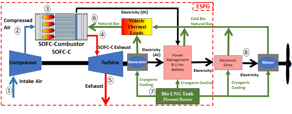
The Solid Oxide Fuel Cell-Combustor (SOFC-C) concept presented in above addresses many challenges a Fuel Cell-Gas Turbine system will have in aerospace applications. The SOFC-C utilizes the gas turbine combustor casing as the hot box. By taking advantage of the temperature rise during compression and the combustion of anode off-gas, the SOFC-C eliminates the recuperating heat exchanger usually required for cathode flows, greatly reducing the size and weight (thermal mass) of the system. In the SOFC-C, fuel (bio LNG) enters the system from the right (thermodynamic state 6) and is partially reformed in the fuel manifold, then enters SOFC providing hydrogen rich gas for electrochemical reactions. The anode off-gas exiting the SOFC then is either recirculated or mixes with warm compressed air from the turbogenerator (TG) compressor (state 2) and undergoes combustion (state 3). The combustion products with plenty of residual oxygen (~19% mol fraction) enter the cathode side of the SOFC providing the oxidant for electrochemical reactions. The compressor air temperature at state 2 will vary between 165-458°C during operation between altitudes of 1,000 ft to 35,000 ft and 50-100% load. The direct combustion of the anode off-gas prior to entering the cathode at state 3 provides precise control of the cathode inlet temperature by manipulating the fuel flow (fuel utilization set point) into the SOFC-C. This feature provides an innovative solution with a high-power density, and direct control of the SOFC temperature during changing loads and altitudes without adding thermal mass. The SOFC-C was initially explored for high-power density, but it also maintains high fuel-to-electric efficiency (>60% during cruise) with rapid startup and load following capability (>30% load change)[1], [2]. Rapid startup less than 30 minutes to full power has been demonstrated by having direct control of the cathode inlet temperature enabling rapid warmup of the SOFC during startup cycles in the field.
The operation of the SOFC-C-TG to meet power demands on the aircraft during vastly changing operation environments is achieved with only three inputs to the system: fuel control valve to maintain desired fuel utilization and cathode inlet temperature, TG generator load to maintain desired shaft speed and air mass flow, and SOFC load for maintaining total power (SOFC-C and TG power) produced by SOFC-C-TG. Note, large high temperature valves for cathode bypass or bleed, additional combustors/fuel valves, and cathode injectors or high temperature blowers are not required for the SOFC-C-TG system.
The SOFC-C concept in is the primary focus for development in the project, but the concept can be leveraged further for an overall energy optimized electric aircraft. The schematic above presents the SOFC-C-TG power generation technology integrated with bio LNG (bLNG) chemical and thermal energy storage (state 7), and electric drive system for propulsion (state 8). The integrated propulsion, power and thermal management system (IPPTS) provides an elegant solution for electrification of large commercial aircraft [2]. The team has extensive experience with SOFC stack development, pressurized operation, gas turbine design and development, and modeling and simulation of IPPTS.
1R. R. Sinnamon, “Analysis of a Fuel Cell Combustor in a Solid Oxide Fuel Cell Hybrid Gas Turbine Power System for Aerospace Application,” Wright State University, 2014.
2V. A. Chakravarthula and R. A. Roberts, “Transient analysis of an innovative cycle integrating a SOFC and a turbogenerator for electric propulsion,” in Proceedings of the ASME Turbo Expo, 2017, vol. 3
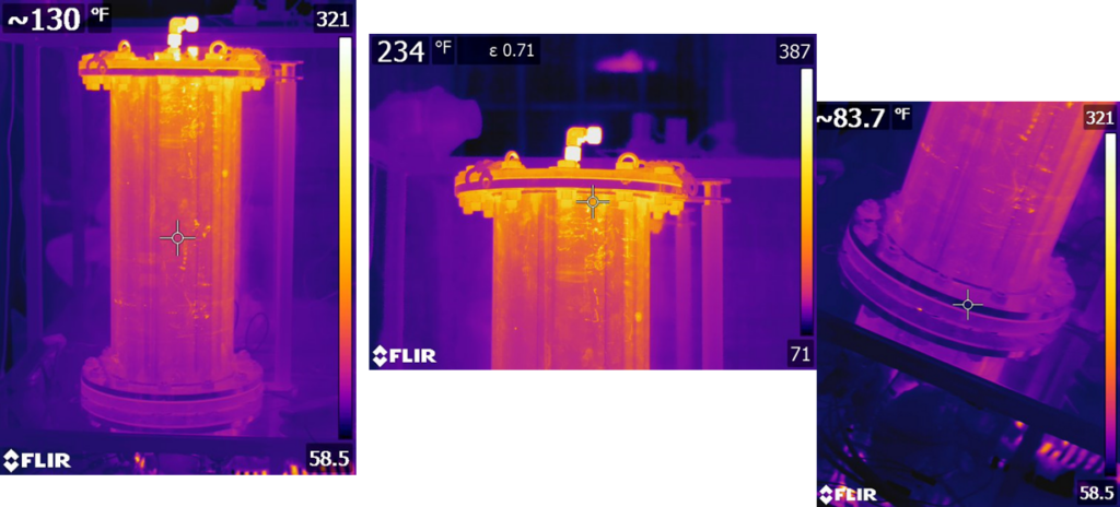
Commissioning of Pressurized SOFC Test Stand
The test stand has been tested at both elevated pressure and temperature. Below are some thermal images of the test vessel housing the SOFC.
Pressurized SOFC Testing
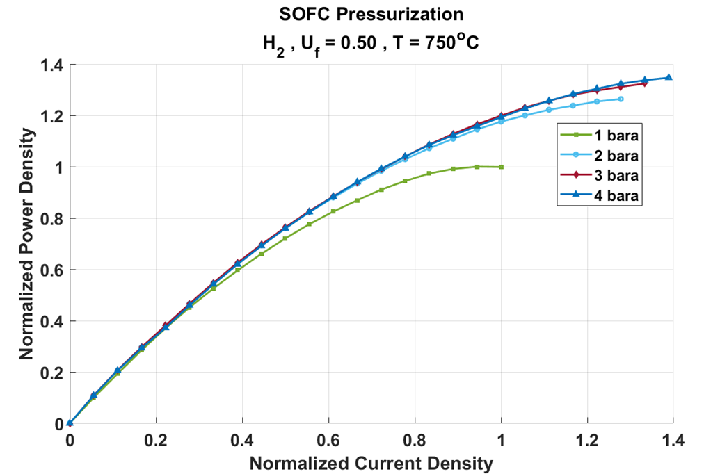
We successfully completed a series of pressurized tests in the first quarter of the project. The pressurized testing is showing promising results.
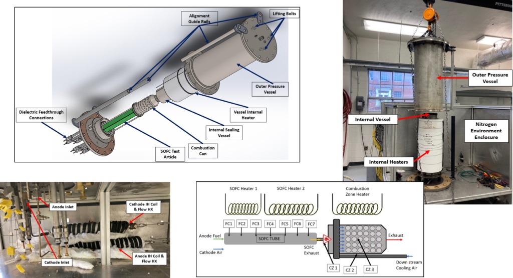
Pressurizing the SOFC tubes to 4 bar increased the power density of the SOFC tubes by 35%.
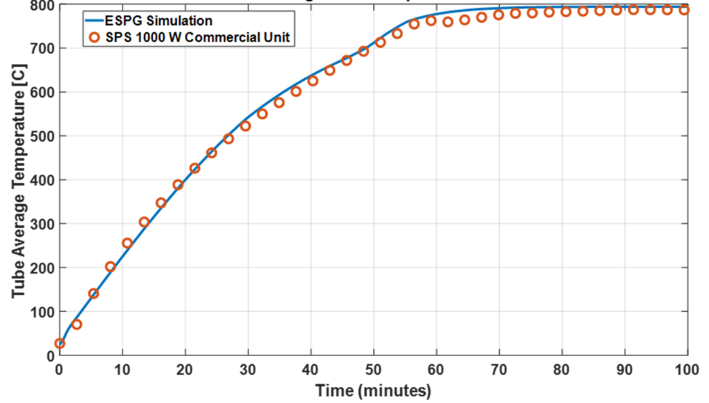
Rapid Startup Verification
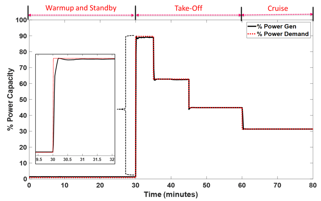
Vehicle level dynamic modeling tools were verified to match the measured data of commercial fielded units. The vehicle simulation tools were used to demonstrate the SOFC-C-TG ability to be rapidly preheated and loaded to full power in less than 30 minutes.
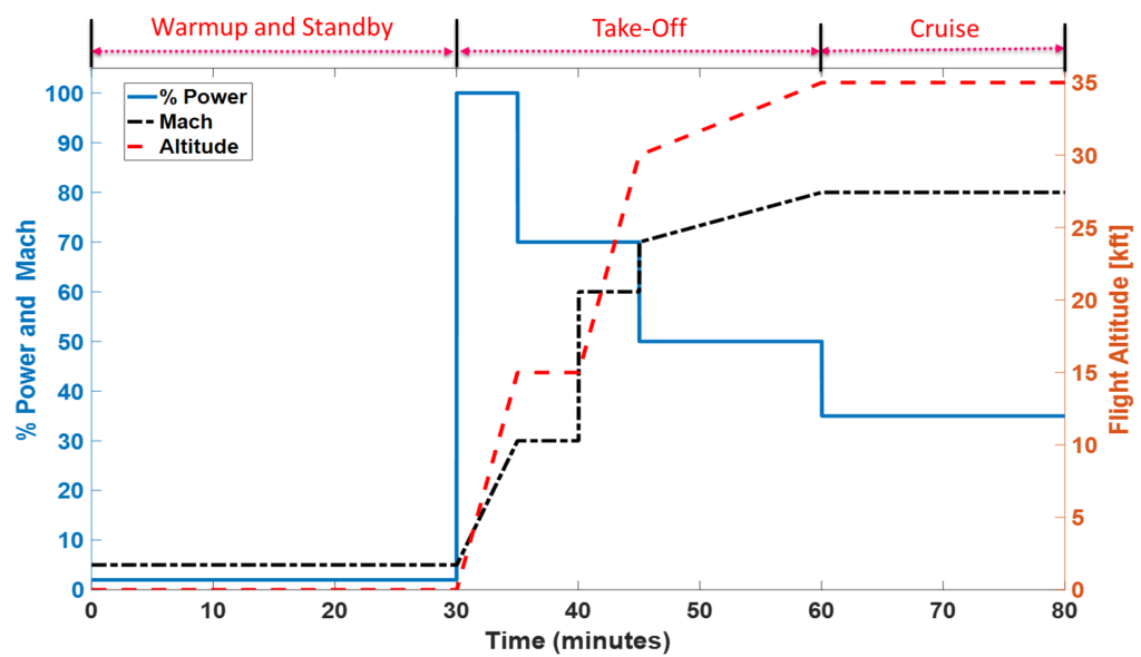
Flight Simulation
A notional flight profile was simulated with preheat, take-off, and cruise segments below. The SOFC-C-TG was preheated and prepared for take-off in 30 minutes. The flight was simulated from sea level to 35,000 ft cruise with a max speed of Mach 0.8.
The SOFC-C temperature reaches operating temperature in 15 minutes with take-off at 30 minutes. During flight the temperature profile within the SOFC-C stabilizes with a 20C temperature difference across the SOFC tubes.
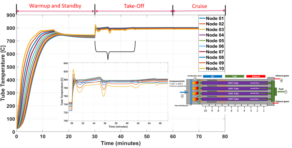
The SOFC-C-TG was able to meet the flight power demands while rejected the dramatic changes in ambient temperature and pressure during flight.